
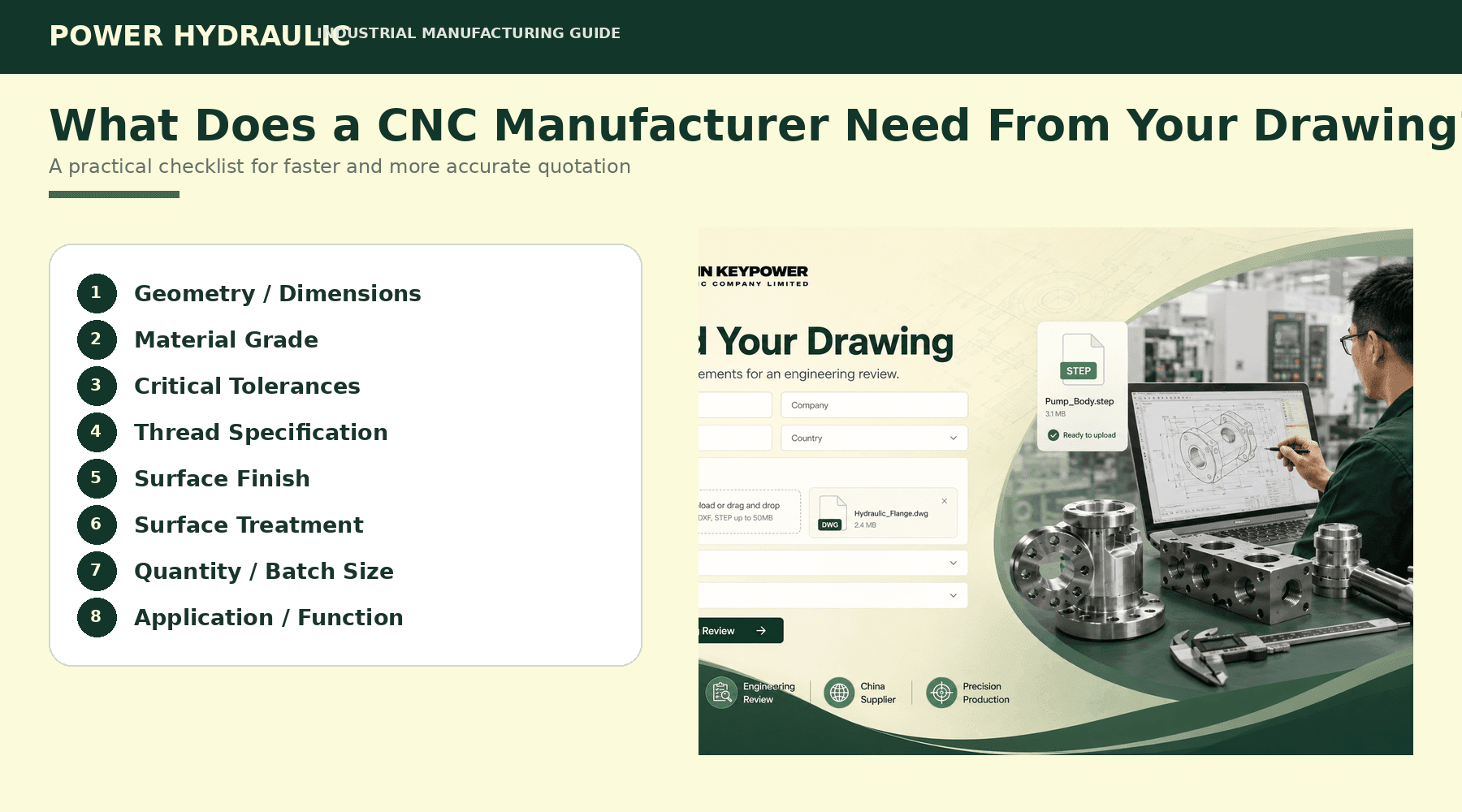
What Information Does a CNC Manufacturer Need From Your Drawing?
A technical drawing does much more than show what a component looks like. Your CNC machining drawing requirements tell the manufacturer which dimensions matter, what material to use, how accurate critical features need to be, and how the finished component should interface with surrounding equipment.
For custom CNC parts, clear technical information can reduce unnecessary communication and improve quotation accuracy.
Industrial buyers do not need a perfect engineering package before making an initial enquiry.
However, providing clear information about geometry, material, tolerance, threads, surface requirements and quantity makes manufacturing evaluation much easier.
Why a 3D Model Alone May Not Be Enough
A 3D CAD model communicates component geometry very effectively.
It can show:
- External shape
- Internal geometry
- Holes
- Pockets
- Curved surfaces
- Assembly interfaces
However, the model may not clearly communicate:
- Which dimensions are critical
- Required tolerances
- Material grade
- Thread standard
- Surface roughness
- Surface treatment
- Quantity
For many CNC projects, the best approach is to provide both a 3D CAD file and a 2D technical drawing.
1. Part Geometry and Dimensions
The manufacturer needs enough dimensional information to understand the finished component.
Important features may include:
- Overall length
- Outside diameter
- Internal bore
- Hole diameter
- Hole spacing
- Slot dimensions
- Wall thickness
- Thread depth
- Flange dimensions
Avoid adding unnecessary duplicate dimensions.
Instead, clearly identify the dimensions that directly affect assembly or function.
2. Material Specification
The drawing should identify the material whenever possible.
Common machining materials include:
- Stainless steel
- Carbon steel
- Alloy steel
- Aluminum
- Brass
A note such as “steel” may not provide enough information.
Different grades can change:
- Strength
- Corrosion resistance
- Machinability
- Surface treatment options
- Cost
If you have not selected a material, provide information about the application so the requirement can be reviewed.
3. Critical Tolerances
Not every dimension needs an extremely tight tolerance.
Unnecessarily tight tolerances can increase machining and inspection complexity.
A useful drawing distinguishes between:
- General dimensions
- Critical mating features
- Precision bores
- Sealing surfaces
- Position-sensitive holes
- Functional interfaces
For example, on a hydraulic adapter, the general exterior geometry may allow more dimensional flexibility than the thread or sealing surface.
Marking critical dimensions clearly helps the manufacturer focus machining and inspection where it matters most.
4. Thread Specifications
Thread information should always be explicit.
Useful information includes:
- Thread standard
- Nominal size
- Pitch
- Male or female
- Thread depth
- Thread length
- Sealing interface
Industrial components may use:
- Metric
- BSP
- BSPP
- BSPT
- NPT
- UNF
- Other customer-specified threads
Two visually similar threads can still be incompatible.
Clearly defined thread information reduces this risk.
5. Surface Finish Requirements
Some machined surfaces perform important functional roles.
Examples include:
- Sealing surfaces
- Bearing areas
- Sliding interfaces
- Mating faces
If a specific surface roughness matters, identify it on the drawing.
Avoid specifying unnecessarily strict surface finishes across the entire component.
That can increase machining time without improving actual performance.
6. Surface Treatment
A CNC machined part may require secondary surface treatment.
Possible options include:
- Zinc plating
- Nickel plating
- Passivation
- Anodizing
- Black oxide
- Polishing
- Brushing
Surface treatment can affect final dimensions and production planning.
Clearly state the required treatment before production.
7. Quantity
Quantity directly affects manufacturing planning.
The supplier needs to know whether the project requires:
- One prototype
- Five development parts
- Twenty trial pieces
- Fifty parts
- One hundred parts
- Recurring low-volume production
If possible, provide both the immediate order quantity and expected future demand.
For example:
Prototype: 5 pcs
Expected repeat order: 100 pcs per batch
This provides useful commercial and production context.
8. Application Information
Basic application information can help the manufacturer understand the functional importance of the component.
Examples include:
- Hydraulic system
- CNC equipment
- Automation machinery
- Pump connection
- Replacement component
- Metal hose fitting
- Industrial assembly
This is particularly useful when the part includes unusual geometry or specialized interfaces.
What File Formats Can You Send?
STEP / STP
STEP files provide useful 3D geometry for many CNC projects.
DWG / DXF
DWG and DXF work well for 2D geometry and engineering drawings.
PDF drawings provide an easy way to communicate:
- Dimensions
- Tolerances
- Threads
- Notes
- Surface requirements
Physical Sample
If no drawing exists, an existing component may provide a starting point for measurement and reverse-engineering evaluation.
What If You Only Have a Physical Sample?
Older machinery often uses components with no available technical drawing.
A physical sample may allow the manufacturer to inspect:
- Overall geometry
- Threads
- Hole locations
- Bore dimensions
- Mating surfaces
- Functional interfaces
However, worn components require careful interpretation.
Wear, corrosion,n and deformation may have changed their dimensions.
Application photographs and information about surrounding components can therefore be very useful.
CNC RFQ Checklist
Before requesting a quotation, prepare as much of the following as possible:
Drawing / CAD File
Material
Quantity
Critical Tolerances
Threads
Surface Finish
Surface Treatment
Application
Inspection Requirements
You do not need every item for your first enquiry.
Start with what you have.
Common Drawing Problems That Delay CNC Quotations
Missing Material
The drawing shows complete geometry but does not identify a material.
Unclear Threads
The CAD model contains a threaded feature, re but the drawing does not specify the thread standard.
Unnecessary Tight Tolerances
Every dimension has an extremely tight tolerance even when only several dimensions affect function.
Conflicting Revisions
The PDF drawing and STEP model represent different revisions.
Missing Quantity
The manufacturer cannot determine whether the project requires a prototype or production batch.
Keeping the engineering files organized can significantly simplify communication.
From Drawing to Finished CNC Part
A typical custom CNC project follows a workflow such as:
Drawing Review → Material Confirmation → Manufacturing Planning → Prototype / Production → Inspection → Shipment
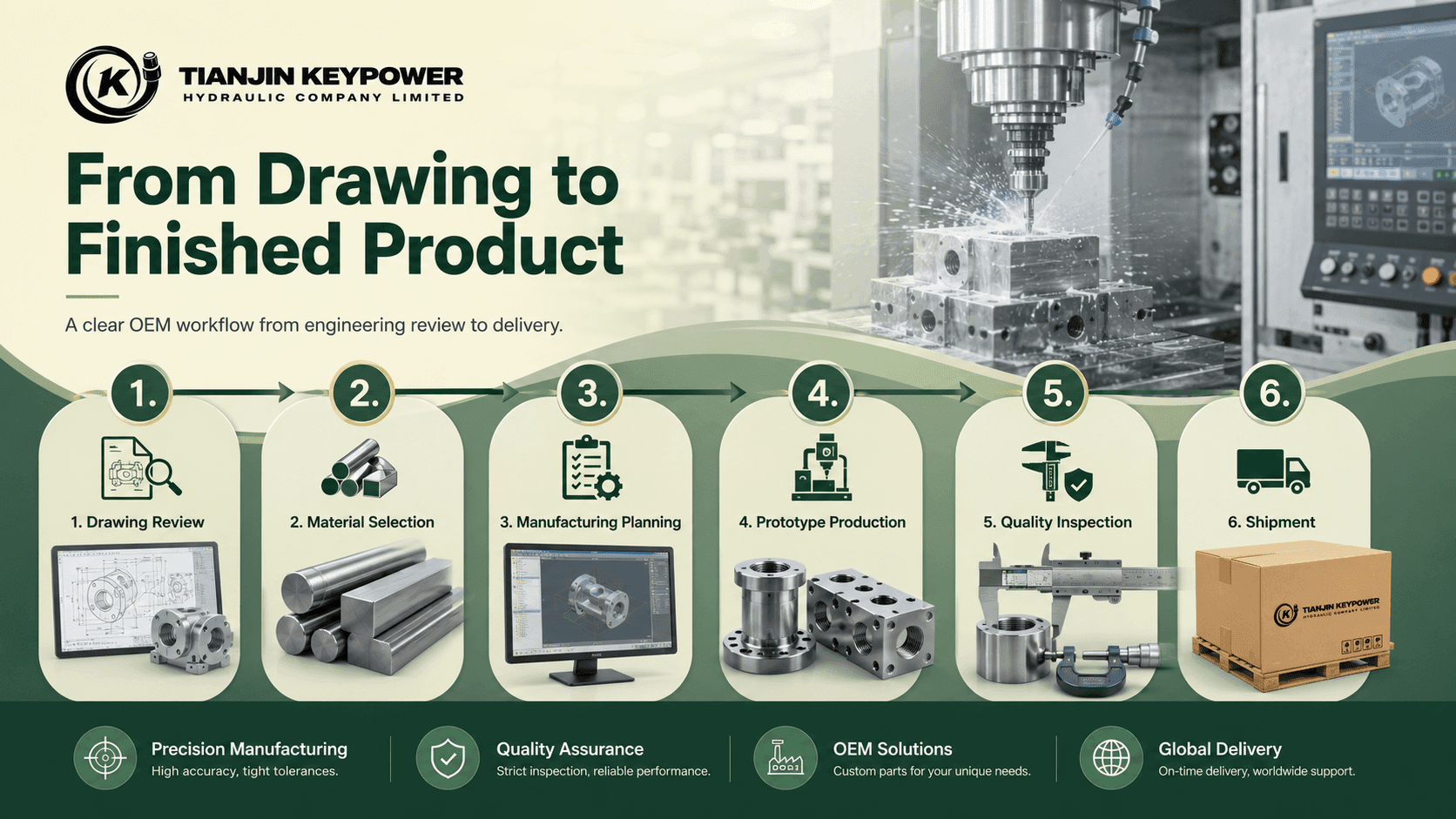
For new or critical components, beginning with a prototype or small batch can reduce the risk of discovering problems after a large production run.
FAQ
Do I need both a 2D drawing and a 3D CAD model?
Not always, but providing both often communicates geometry and technical requirements more clearly.
Can a manufacturer work from a STEP file?
Yes, but additional information such as material, quantity, tolerance, and surface requirements may still be necessary.
What if I do not know the required tolerance?
Identify the most important mating and functional features and provide information about the application.
Can a component be manufactured from a physical sample?
A sample can provide a useful starting point when the original drawing is unavailable.
Can I order only 50 or 100 CNC parts?
Many custom CNC projects involve low-volume quantities. The practical MOQ depends on the geometry, material, and manufacturing process.
Have a Drawing Ready?
Send us your CNC machining drawing requirements:
PDF · STEP · DWG · DXF · Material · Quantity · Application
Our team can review the manufacturing CNC machining drawing requirements for your project.


